CyberCode Academy Podcast Por CyberCode Academy arte de portada

CyberCode Academy

CyberCode Academy

De: CyberCode Academy
Escúchala gratis

Exclusivo para miembros Prime | $0.99/mes por 4 meses + $20 de crédito en Audible

$8.99 al mes después de 4 meses. Consulta términos y condiciones.
Welcome to CyberCode Academy — your audio classroom for Programming and Cybersecurity.
🎧 Each course is divided into a series of short, focused episodes that take you from beginner to advanced level — one lesson at a time.
From Python and web development to ethical hacking and digital defense, our content transforms complex concepts into simple, engaging audio learning.
Study anywhere, anytime — and level up your skills with CyberCode Academy.
🚀 Learn. Code. Secure.

You can listen and download our episodes for free on more than 10 different platforms:
https://linktr.ee/cybercode_academy
Copyright CyberCode Academy
Diario Educación
Episodios
  • Course 45 - IE Data Center Network Design | Episode 3: Mastering Virtual Port Channels
    Oct 5 2026
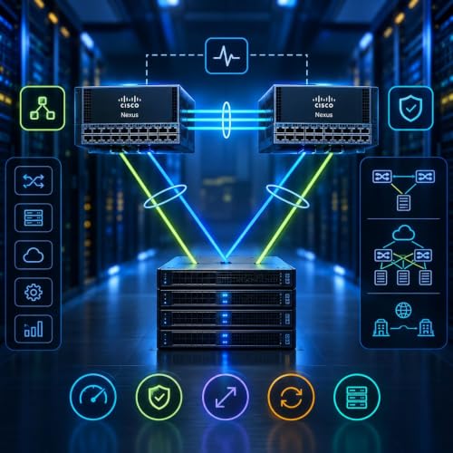
    Virtual Port Channel (vPC) Design: Architecture, Best Practices, and Advanced StrategiesEpisode OverviewHow can two physical Cisco Nexus switches provide a highly available, active-active connection to the same downstream device while maintaining Layer 2 loop prevention?Virtual Port Channel (vPC) provides a multi-chassis link aggregation architecture that allows two switches to present a coordinated logical interface to connected devices. The result is active-active connectivity, improved bandwidth utilization, device-level redundancy, and rapid recovery from individual link or switch failures.In this episode, we explore the architecture and operational principles behind vPC on Cisco Nexus platforms, beginning with its core building blocks and progressing through deployment best practices, hardware redundancy, control-plane considerations, and advanced integration with technologies such as FabricPath, VXLAN EVPN, and Data Center Interconnect (DCI).1. Understanding Multi-Chassis Link AggregationTraditional link aggregation normally operates between a device and a single logical switching endpoint.Multi-Chassis Link Aggregation (MLAG) extends this concept by allowing a downstream device to form a single logical port channel across two physical switches.With vPC, the connected device can establish an LACP-based port channel spanning both Nexus peers.This provides:- Active-active forwarding.- Link-level redundancy.- Switch-level redundancy.- Better bandwidth utilization.- Reduced dependence on blocked Layer 2 links.- Faster recovery from individual failures.A fundamental architectural constraint is that a traditional vPC domain consists of two peer switches working together as a logical pair.2. The Three Core Components of a vPC DomainA functional vPC architecture relies on three primary components:Peer Keepalive LinkThe peer keepalive mechanism provides a dedicated health-check path between the two vPC peers.Its primary purpose is determining whether the peer switch is still reachable and avoiding ambiguous failure conditions.The keepalive mechanism uses IP-based communication and should be designed independently from the primary peer-link forwarding path where possible.Peer LinkThe peer link is the primary inter-switch connection between the vPC peers.It carries important synchronization and control-related information and can also carry specific Layer 2 traffic between the switches.The peer link should therefore be designed with sufficient bandwidth and redundancy for the expected traffic and failure scenarios.Member PortsvPC member ports are the interfaces that connect downstream devices to the vPC peers.A downstream server, switch, appliance, or other supported device can establish a single logical port channel using physical links connected to both Nexus switches.The resulting topology is:Downstream Device → vPC Member Ports → Nexus Peer 1 + Nexus Peer 23. vPC Loop Prevention and Active-Active ForwardingOne of the most important characteristics of vPC is its approach to Layer 2 loop prevention.The vPC architecture prevents traffic received through the peer link from being unnecessarily forwarded back out through a vPC member port in situations where that could create a loop.At the same time, vPC allows connected devices to use links toward both peers simultaneously.This creates a useful combination:Active-Active Forwarding + Controlled Layer 2 Loop PreventionvPC can also integrate with first-hop gateway technologies such as HSRP, allowing both switches to participate in forwarding while presenting a consistent gateway to connected hosts.4. Designing the vPC DomainSuccessful vPC deployments begin with careful domain planning.Important design considerations include:- Correct vPC domain identification.- Consistent peer configuration.- Reliable peer-keepalive connectivity.- Redundant peer-link design.- Consistent VLAN and port-channel parameters.- Appropriate vPC member configuration.The configuration process should be approached methodically rather than treating the peer link as simply another trunk.The peer-keepalive mechanism should be established and verified before relying on the peer-link relationship.This helps reduce ambiguity during initial deployment and troubleshooting.5. Aligning vPC and Port-Channel IdentifiersOperational simplicity matters in large data center environments.Where appropriate, aligning the vPC identifier with the corresponding port-channel identifier can make configurations easier to understand.For example:vPC 10 ↔ Port-Channel 10Consistent identifiers can simplify:- Configuration reviews.- Troubleshooting.- Documentation.- Operational maintenance.- Cross-device comparison.The exact numbering strategy can vary by organization, but consistency is more important than any particular number.6. Designing for Hardware FailureRedundancy should not stop at the switch chassis.If both sides of a critical vPC topology depend on the same physical line card or module, a ...
    Más Menos
    24 m
  • Course 45 - IE Data Center Network Design | Episode 2: Modern Layer 3 Data Center Design
    Oct 4 2026
    Designing Resilient Layer 3 Data Center Networks: Mobility, Convergence, and Service IntegrationEpisode OverviewModern data centers increasingly rely on routed Layer 3 fabrics to achieve the scalability, availability, and operational flexibility demanded by virtualized workloads.In this two-part episode, we explore the architecture behind resilient Layer 3 data center networks, focusing on three foundational objectives:- IP mobility and optimized ingress paths- High availability and rapid convergence- Layer 4–7 service integrationThe episode builds upon modern leaf-spine and VXLAN architectures, showing how distributed gateways, host-mobility technologies, fast failure detection, resilient control planes, multicast redundancy, and VRF-based service insertion work together to create highly available data center fabrics.Part I: IP Mobility and High Availability1. Moving Beyond Traditional Data Center GatewaysTraditional data center designs often rely on centralized distribution-layer gateways and first-hop redundancy protocols such as HSRP or VRRP.Modern VXLAN-based fabrics can distribute the default gateway across multiple leaf switches instead.With an Anycast Gateway, multiple leaf switches can share the same gateway IP and MAC address within a tenant VRF.This provides a consistent first-hop gateway regardless of which leaf switch a workload connects to.The result is a more distributed architecture that supports:- Workload mobility.- Consistent default-gateway addressing.- Reduced dependence on centralized gateways.- Improved traffic locality.- Greater scalability.2. VXLAN and Anycast Gateway MobilityVirtual machines may move between physical hosts or leaf switches while retaining their existing IP addressing.A distributed Anycast Gateway helps preserve the first-hop network identity of the workload throughout the fabric.Instead of forcing traffic toward a centralized gateway, the workload can use the locally available gateway on whichever leaf it is attached to.This reduces unnecessary traffic traversal and allows the data center fabric to remain aligned with workload placement.The conceptual architecture becomes:Workload → Local Anycast Gateway → VXLAN Fabric → Destination WorkloadRather than:Workload → Centralized Gateway → Distribution Layer → Destination3. Extending Connectivity Across Multiple FabricsWorkload mobility may sometimes extend beyond a single data center fabric.Technologies such as VXLAN EVPN and OTV can provide mechanisms for extending Layer 2 connectivity across Layer 3 transport between different locations.This allows organizations to build interconnected fabrics while maintaining logical network continuity where the architecture requires it.However, extending Layer 2 across sites introduces additional design considerations around:- Failure domains.- Broadcast and unknown-unicast traffic.- Routing efficiency.- Convergence.- Operational complexity.The objective should therefore be controlled extension rather than simply creating one enormous Layer 2 domain.4. Optimizing Ingress Traffic with LISPMulti-site workload mobility introduces another challenge: where should incoming traffic enter the network?Consider a workload whose subnet is advertised from multiple data center locations.Traditional routing may select a border location based on the available routing topology rather than the actual location of the individual workload.This can produce inefficient traffic paths sometimes described as trombone routing, where traffic enters one location and then travels across the network to reach the workload's actual location.5. Separating Endpoint Identity from LocationLocation Identifier Separation Protocol (LISP) addresses this challenge by separating two concepts:- Endpoint Identifier (EID): Identifies the endpoint.- Routing Locator (RLOC): Identifies where the endpoint is reachable.A mapping system associates the endpoint identity with its current routing location.This allows the network to determine where a particular workload actually resides instead of relying exclusively on aggregate subnet routing.The conceptual process becomes:Endpoint Identity → Mapping Lookup → Current Fabric Location → Optimized IngressHost-specific routing information can then direct traffic toward the fabric currently hosting the workload.This approach is particularly useful when the same logical network is available across multiple data center locations.Part II: Rapid Convergence and Service Integration6. Scaling Through a Clos ArchitectureHigh availability begins with the physical topology.Modern data centers commonly use a Clos or leaf-spine architecture, where additional capacity can be introduced by scaling horizontally.Instead of relying on a small number of increasingly powerful chassis, organizations can add additional spine or leaf capacity as requirements grow.A typical architecture provides:Leaf → Multiple Spines → LeafBecause each leaf can connect to multiple spines, the ...
    Más Menos
    23 m
  • Course 45 - IE Data Center Network Design | Episode 1: Layer 2 Data Center Design
    Oct 3 2026
    Layer 2 Data Center Design & Endpoint MobilityEpisode OverviewModern data center networks must do more than simply connect servers. They must support workload mobility, continuous availability, scalable architectures, and intelligent integration of network services.In this episode, we explore the architectural principles behind high-performance Layer 2 and data center fabrics, beginning with the limitations of traditional Spanning Tree Protocol and progressing toward Virtual Port Channels, leaf-spine architectures, VXLAN, ECMP, and Layer 4–7 service integration.The goal is to understand how modern data center designs preserve the benefits of Layer 2 connectivity while introducing the scalability, redundancy, and fast convergence associated with Layer 3 architectures.1. Defining the Data Center Network Design GoalsA modern data center architecture should address three fundamental requirements.Endpoint and Workload MobilityVirtual machines and other workloads may need to move between physical hosts or network locations without requiring major changes to their network identity.The underlying network therefore needs to maintain connectivity while workloads move across the infrastructure.High AvailabilityCritical network paths should avoid single points of failure.Ideally, redundant links should not sit idle waiting for a failure. An active-active architecture allows available bandwidth to be used while maintaining redundancy.Services AwarenessApplications frequently depend on network services such as:- Firewalls.- Load balancers.- Proxy servers.- Other Layer 4–7 services.The network architecture must provide a clean mechanism for integrating these services into traffic flows.2. Understanding the Limitations of Spanning TreeTraditional Spanning Tree Protocol (STP) was designed to prevent Layer 2 switching loops by placing redundant paths into a blocked state.While this provides loop prevention, it introduces several challenges in modern data centers.Redundant links may remain unused during normal operation, resulting in inefficient bandwidth utilization.STP convergence can also introduce disruption during topology changes. Changes may trigger Topology Change Notifications (TCNs) and associated MAC-table behavior, potentially causing temporary flooding while the network relearns forwarding information.Another concern is that traditional Layer 2 designs can become increasingly difficult to scale as the number of endpoints and redundant paths grows.These limitations motivate architectures that can use multiple physical paths simultaneously.3. Virtual Port ChannelsVirtual Port Channels (vPC) provide a mechanism for presenting multiple physical switches as a logical port-channel endpoint from the perspective of connected devices.This allows a downstream device to establish links toward two switches while treating them as a single logical connection.The result can be represented conceptually as:Traditional Redundancy:Active Link + Standby LinkvPC-Based Design:Active Link + Active LinkBoth paths can therefore participate in forwarding while providing redundancy if one physical connection or switch becomes unavailable.4. Back-to-Back vPC ArchitecturesThe vPC concept can also be extended through back-to-back vPC designs, allowing multiple network devices to participate in highly available Layer 2 connectivity.The objective is to transform physical topologies that would traditionally require STP to block redundant paths into architectures where those paths can actively contribute to forwarding.This approach helps address two competing requirements:Redundancy + Bandwidth UtilizationInstead of maintaining unused physical links solely for failover, the architecture can make better use of available network capacity.5. Moving Toward Leaf-Spine ArchitecturesAs data centers scale, traditional hierarchical designs can become difficult to manage and expand.The leaf-spine architecture addresses this challenge by creating a predictable, horizontally scalable topology.In a typical fabric:- Leaf switches connect servers and endpoints.- Spine switches provide the high-speed interconnection between leaf switches.- Multiple equal-cost paths are available between network endpoints.This creates a highly predictable forwarding environment in which additional capacity can be introduced by expanding the fabric.6. Equal-Cost MultipathingEqual-Cost Multipathing (ECMP) allows traffic to use multiple paths with equivalent routing costs.Rather than relying on a single preferred path while keeping alternatives idle, ECMP can distribute traffic across available paths.This provides several benefits:- Better utilization of network links.- Greater aggregate bandwidth.- Redundancy across multiple paths.- Scalable horizontal expansion.- Faster recovery when a path becomes unavailable.The architecture therefore shifts redundancy from blocked Layer 2 links toward active Layer 3 paths.7. VXLAN: Extending Layer 2 Across Layer 3One of the central ...
    Más Menos
    26 m
adbl_web_anon_alc_button_suppression_t1
Todavía no hay opiniones